
PLACEMENT OF SYSTEM OPERATION SWITCHES
At this point, it is time to find a spot for the option and operation switches. These are the DIP-Switch that controls the sound system's mode of operation, the volume control switch, the Canyon-Chuff switch, and the battery disconnect switch that is being added. In reading the instructions contained in Phoenix's kit, they recommend installing the switches on the bottom side of the tender. A better idea is to install all the option and operation switches inside the Brake house. This location is easier to get to and has enough space to allow all the switches to be in one area, but out of general sight.


The first step is to remove the brake house from the upper section of the tender. As seen in the two pictures above, by removing the 4 bolts on the base of the brake house, the entire house structure is separated from the upper tender.

The photo above shows the upper section of the tender with the brake house removed. It is now time to layout and mark where the switches will be mounted on the brake house base. I mark the hole location points with a pencil and set them with a punch and small hammer, as shown in the picture below.

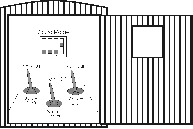
After the holes have been located, I use my battery drill to drill a 1/16" pilot hole for each of the 3 switch locations. The initial pilot holes are next opened up to a final size of 5/16". And the three switches are then installed. The pictures below show the final hole placement and identifies which switch is to be installed where.


Now, in looking closely at the brake house, a slight modification of the light-bracket will improve the interior look and help keep the light's wiring from interfering with the operation of the switches that are to be housed within the brake house itself.

To remove the brake house's light bracket, the two bolts in the front wall of the brake house were extracted. This can be seen in the picture above. Upon removal, the house itself is set aside.


The above-left picture shows the brake house's light and light-bracket. A hole was drilled in the back portion of the light-bracket to allow the light wiring to route smoothly down the brake house's front wall. The above-right photo, shows the modified light-bracket and the light's wiring slipped through the hole. The brake house light is now ready to be re-installed.

Above, the light has been re-installed and the sound system's DIP-Switch has been mounted to the front wall of the brake house. Note the black weave tape that was put on to the front wall before mounting the DIP-Switch; the material is indoor/outdoor carpet tape. This carpet tape is used in this instance to adhere and insulate the DIP-Switch from shorting against the brass of the brake house's front wall. The pictures below are close-ups of the brake house light and wiring.


The picture below show everything assembled and the brake house re-installed. Note the switches in the floor are relatively easy to get to, and yet hidden from plain view. A nice added touch would be a brakeman figure modified to slip over the center, volume control switch -- I'll leave that up to the new owner. The DIP-Switch on the front wall almost resembles some type scale switch box, but no such animal really lived in this house.

With the installation of the mode and option switches as shown above, it is now time to mount the battery and sound board and wiring the system together.

As a follow up after the installation was completed, the illustration above was created, it shows the final placement of all the switches and their states. A copy of this illustration is provided for the future owner as reference.